Basic concept PLC 5 and SLC 500 (Allen Bradley PLC’S) simulation

Dear all hands

Allen Bradley PLC now offer more friendly tool to learn their PLC programming.

To learn programming Allen Bradley PLC software we need is:
1. RSlogix emulate
2. RS ladder 500
3. RS link

RS Logix emulate function as follows:
a. Mimicked the behavior of Allen Bradley PLCs (PLC-5 series or SLC 500)
b. Execute our diagram ladder
c. Allows us to predict what would happen if a program inserted into a real PLC.
When a PLC executes the program then what happens is the process of scanning program (can be 10 to 50 times per second), in this scanning process occurs:
1. Checking table data updates caused by the response I / O
2. Program execution, followed by updating the data table
3. Updating I / O based on the data table
This scanning process can be described as follows:

Since in our simulations are not connected to the I / O module is as a substitute for the Input module is a debug file. Debug file is part of the ladder diagrams are used to simulate the input.

RSLogix Emulate uses your computer’s CPU to scan the rungs in your ladder program. The rungs in your program read inputs from and write outputs to the data table stored offline with your ladder logic project. The offline data table is

also active during emulation. RSLogix Emulate reads the ladder program and data table into your computer’s

memory before executing the ladder logic. The files on your disk are not affected by the emulator. The basic order of events during emulation is no different from when a processor runs a project. RSLogix Emulate scans your rungs, pauses to update the output and input image tables, and scans your rungs again. (During normal operation, RSLogix Emulate repeats the program scan until you tell it to stop.There are other scanning modes you can use.)

Basic Instruction Glofa ladder diagram programming tutorial part II : Up Counter (CTU)

Dear all hands,

It’s the third my posting about glofa ladder programming tutorial. So you can see this post as successor of my second post about glofa programming tutorial.In this post I want to talk about CTU or up cainter basic instruction. Basically CTU is incremental counter.

Ladder symbol for CTU (UpCounter).


Explanantion :

CU : Up counter pulse input, : triggering input for start increment counting,

R : Reset input, when its value is , CV value will reset back to zero..

PV : Preset Value,: counter maximum setting value, type data integer with value range between :-32768 – 32768

Q : Up counter output, counter output that will be executed if CV value reach PV value.

CV : Current Value, recent counter value being displayed.

Ladder diagram example for CTU :

In glofa ladder diagram above, Counter PV value is 10, when “%Q0.0.0” on, then counter will start count from 0 to 10, when CV reach its max value (10), then output counter (OUT1) will on, its make output “%Q0.0.0” also on and PV value will reset back . If. Jika input “%I0.0.1” (reset input) on, then i current value (CV) will also back to zero.

Glofa ladder diagram programming basic instruction PART 1

Dear all hands

After we understanding the basic concept of glofa ladder diagram pogramming , we now can start with glofa ladder diagram programming basic instruction, for increase speed our learning process of glofa programming we can summary the most often used basic instruction.

Counter Function :

CTD or Counter down

Ladder symbol for CTD :


Explanation :

CD : Down counter pulse input, input trigger for starting counter. When CTD is ON , CTD will count in decrement counting.

LD : Loads preset value,: If LD has value 1 , CV value will be restored as PV value.

PV : Preset Value: is a maximum setting value of the counter. Its range between :-32768 – 32768 , with integer data type.

Q : Down counter output,: counter output that will be executed if the counter reach 0 or negative value..

CV : Current Value, : is the value being displayed when counter incounting condition.

Figure below depicted an example ladder diagram programming use CTD , counter basic instruction


Ladder diagram program above ,maximum value is 1, when input “%Q0.0.0” , then counter will count decremently fro 10 to , so that CV value reach zero or negative value then output counter (OUT1) will on, and output “%Q0.0.0” also on. If input “%I0.0.1” on, the current value (CV) will back to Preset Value (PV) in this chase is 10.

The difference between difference amplifier and instrumentation amplifier

Dear all hands

Some time we need more powerfull amplifier, specially when we deal with transducer that its output is very small such of thermocouple. And the answer Is instrumentation amplifier.
Why difference amplifier did not adequate on such application? The difference amplifer is satisfactory for low impedance source, buts its input impedance is too low for high output impedance sensor. Furthermore , If the input signal very low level and inckude signal noise, the difference amplifier is unable to extract a satisfactory difference signal. The solution is not difference amplifier but instrumentation amplifier.
Instrumentation amplifier has the following characteristic :
a. Instrumentation amplifier has Very high input impedance
b. Large CMMR: CMMR is the ratio of the difference mode gain to the common mode gain. The difference mode gain is the amplification factor for the difference between the input signals, and the common mode gain is the amplification factor for the average of the input signal. For an ideal instrumentation amplifier and difference amplifier , the common mode gain is zero, implying an infinite CMMR. But sure the ideal instrumentation amplifier isnot exist.
c. Instrumentation amplifier has capability to amplify low level signal in noisy environment (due to high CMMR)
d. Instrumentation amplifier has consisten bandwidth over a large range of gain.
Instrumentation amplifier are commercially available as monolithic IC( ex. AD 5234, AD624 or LM 623). In these instrumentation amplifier ICs , a single external resistor is used to set gain.
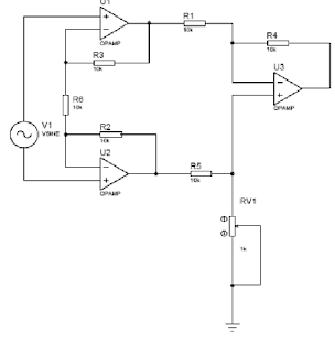
But theorycally, we can made an instrumentation amplifier using op-amp. There are many instrumentation amplifier circuit design , following figure show an instrumentation amplifier circuit use three op-amp.

Three op-amp Instrumentation amplifier circuit simulation using proteus

Dear all hand

As iam said before that theorically we can build our our instrumentation use op-amp. But its very challenging to simulate our instrumentation amplifer before we make it real. As usual we use proteus isi to build and to simulate our instrumentation amplifer .

Very important for us to use ideal op-amp in build instrumentation amplifier circuit that we want to simulate

What we need is:

  1. 3 ideal op-amp
  2. 6 ideal resistor
  3. 1 Vsine
  4. One potentio

And we arrange components above become three op-amp instrumentation circuit below :


The input and output relationship of the instrumentation amplifier above is :

Applying ohm law to R1 gives :

And we can rearrange equation above become :

And finally we get the output :


In this simulation we take R4= R5 .

To view output and input of this instrumentation amplifier we use oscilloscope (located at left bar of Proteus Isis)

Set V1 (sine ) at 4mV and 10 hz , and run simulate , the simulation result depicted below :


Basic Principle work of transistor current source

Dear all hands

Transistor Current source although often neglected are as important and as useful as voltage source. Transistor current source often provide an excellent way to bias a transistors, an transistor current source are unequaled as “active load” for super gain amplifier stage and as emitter source for differential amplifier.

Integrator, saw tooth generator and ramp generator are need current source. Transistor current source also needed in outside world such of in electrophoresis or electrochemistry.

Basic principle work for current source is the circuit capable to hold current at desired value despite the load is change.

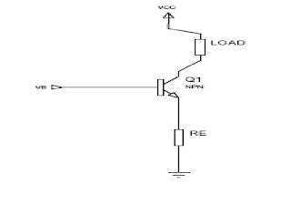
Below is transistor current source circuit with basic principle work :


Basic principle work of transistor current source circuit above is :

  1. Applying VB to the base, with VB > 0,6 v
  2. Ensures that emitter is always conducting :

So

VE =VB-0,6 V

IE = VE/RE = (VB-0,6 v)/RE

But , since IE =IC for very large hfe

IC = (VB-0,6)/RE

From latest expresion, load current in this current source circuit just only depend on RE value, an independent from load value

We can simulate transistor current source circuit above with proteus isis.

Single ended Practical Sensor Amplifiers Circuit with Op-Amp

Dear all hands

Some time when we want to measure a signal we must amplify it before we can measure it. To amplify signal we can use sensor amplifier. Sensor amplifier can easily constructed from op-amp or we can use certain linear amplifier IC devices.

Practical sensor amplifier topology is divided in two category , that is:

  1. Single ended practical sensor amplifier
  2. Differential practical sensor amplifier
  3. Isolated practical sensor amplifier

Figure below show single ended practical sensor circuit with op-amp :

Basically single ended practical sensor amplifier above is inverting amplifier. Its called single ended practical sensor amplifier because in this practical sensor amplifier its input mode is not in differential mode (output from sensor its referenced to ground not with another signal).

Main drawback of this practical sensor amplifier is that it hasn’t very high input impedance. Gain of this sensor amplifier circuit is : -(R2/R1).

But if we need single ended practical sensor amplifier with very high input impedance we can use another single ended practical sensor amplifier as depicted below :

High impedance single ended practical sensor amplifier circuit above basically is a non inverting amplifier, its has very high input impedance and its gain is : 1-(R2/R1)

Tips on earth Resistance Measurement and Improvement

Dear all hands

We know that grounding system is a crucial part in electrical safety system to avoid a man being shodked by electrical current. The main function of grounding system is to give a path for short circuit current and to give same ekuipotensial level in metal body or chase of electrical tool.

Before we decided what kind of grounding system that will we use , we must know the value of earth resistance in the location we will burry grounding rod. Earth resistance commonly determined by it soil type and compositon

Below is table of earth resistance on various soil type :

Table above just only average value of earth resistance, so we must conduct earth resistance measurement before installing gound rod. To conduct earth measurement we can use earth tester. Earth tester is now comerically available.

Earth tester for earth resistance measurement commonly equipped with 3 rod , below is the rod name for earth resistance measurement:

  1. Potential rod
  2. Voltage Rod
  3. Reference rod

For more clear , figure below depicted an earth tester with rod for earth resistance measurement :


A is reference rod

B Is potential rod

C is current rod


For good earth resistance measurement, tree rod above is located with span 5 m each other . Ideally soil with good earth resistance has earth resistance below 5 ohm. And sometime we must conduct earth resistance improvement to meet our need.

To conduct earth resistance improvement with can add or pour salt material in our grounding rod hole but we must careful when chose salt material for earth resistance measurement because it can erode the ground rod. Usually for earth resistance improvement we can use salt from manganese .


Practical DC Differential Amplifier For Sensor Amplifiers Circuit with Op-Am

Practical DC Differential Amplifier For Sensor Amplifiers Circuit with Op-Am

Dear all hand

When we want to supresse interference in our practical sensor amplifier its mean we must use a pratical differential amplifier for sensor amplifier that has ability to suppress interference, and the answer is differential amplifer.

In many system the input leads pickup 60hz from the power line feeds that permeate all electrical building. In single ended practical sensor amplifier , the 60 hz interfering signal treated as valid input.

But in practical differential amplifier the two leads affected equally by the field so they present equal strength signal to the (-) and (+) input. In differential amplifier , just only the difference of two inputs treated as desired signal.

There are two basic configuration of differential amplifier for sensor:

  1. The DC differential amplifier circuit for sensor signal amplifier
  2. Instrumentation amplifier

Below is a figure depicted practical differential amplifier circuit for practical sensor amplifier:


This practical differential amplifier for sensor need to ensure that two input reistance is in balance (R1 = R2) and also feedback resistor in balance (R4=R3), if this two condition is satisfied output will follow this equation : Vout = (Vin+-Vin-) x R3/R1.

Limitation of this practical dc differential amplifier include a reatively low maximum ain and a low input impedance (set by R1 and R2). These problem are overcome in more advanced practical differential amplifier called the instrumentation amplifier.

The most simplest way to attach adsense in wordpress

Dear all hands
Im very happy when my adsense had been approved. But in first time i have difficulty to attach adsense in wordpress. So i try to find in the net the simplest way to attach adsense in wordpress. Luckily after so many failed search to find the simplest way to attach adsense in wordpress i found what is has search. Below is my summary and i think its the most simplest way to attach adsense in wordpress.
My summary on the most simplest way to attach adsense in wordpress :
1. First step : open wordpress an login as admin

2. In plugin menu, choose add plug in an search plugin with adsense as keyword

3. You will be offered with so many adsense plug in, chose daemon adsense plugin , i think via this plugin we can get the most simplest way to attach adsense in wordpress

4. After chose daemon plug in, then install it and activate it.

5. If you finished all steps above, we back to wordpress dashboard6. In wordpress dashboard, chose setting menu (it located in left corner )

7. in ,setting menu choose adsense daemon

8. In adsense daemon there are will be offered for four adsense, for first time its better to chose one adsense only.9. And the final step is to pimp adsense appearance in our web
For me, steps above its the most simplest way to attach adsense in wordpress, but surely its not enough for someone who more advanced in web programming and if you is in this category you can use another adsense plug in. have nice try!