Showing posts with label Instrumentation. Show all posts

The difference between difference amplifier and instrumentation amplifier

Dear all hands

Some time we need more powerfull amplifier, specially when we deal with transducer that its output is very small such of thermocouple. And the answer Is instrumentation amplifier.
Why difference amplifier did not adequate on such application? The difference amplifer is satisfactory for low impedance source, buts its input impedance is too low for high output impedance sensor. Furthermore , If the input signal very low level and inckude signal noise, the difference amplifier is unable to extract a satisfactory difference signal. The solution is not difference amplifier but instrumentation amplifier.
Instrumentation amplifier has the following characteristic :
a. Instrumentation amplifier has Very high input impedance
b. Large CMMR: CMMR is the ratio of the difference mode gain to the common mode gain. The difference mode gain is the amplification factor for the difference between the input signals, and the common mode gain is the amplification factor for the average of the input signal. For an ideal instrumentation amplifier and difference amplifier , the common mode gain is zero, implying an infinite CMMR. But sure the ideal instrumentation amplifier isnot exist.
c. Instrumentation amplifier has capability to amplify low level signal in noisy environment (due to high CMMR)
d. Instrumentation amplifier has consisten bandwidth over a large range of gain.
Instrumentation amplifier are commercially available as monolithic IC( ex. AD 5234, AD624 or LM 623). In these instrumentation amplifier ICs , a single external resistor is used to set gain.
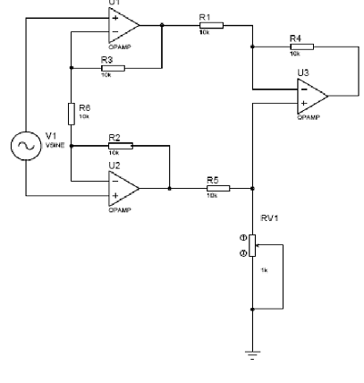
But theorycally, we can made an instrumentation amplifier using op-amp. There are many instrumentation amplifier circuit design , following figure show an instrumentation amplifier circuit use three op-amp.
Compensating and Extension Cable for Thermocouple

Compensation cables for the thermocouples are of the same type as the thermocouple. They are a little bit smaller in size, depending of the distance to be covered and a X suffix. So, a T type thermocouple extension wire is TX cable.
A smart transmitter compensates for the thermocouple created by the junction of the extension wire to the connection screws by measuring the ambient temperature and adding or subtracting the corresponding millivolts in the smart transmitter software running in the microprocessor. Below is image for this cable
The smart transmitter cannot compensate for a copper extension wire, it's not a current practice.


If you have to install terminal blocks in a thermocouple junction box, you have to use special compression type terminals (Entrelec manufacture them) which compress the thermocouple wire with the extension wire, so no cold junction generating voltage is created.
If you have a lot of thermocouple to send to a remote site and in order to lower the extension wire costs you can use copper wires. But, here's the trick. If you look at thermocouple table, you can see that all thermocouple types generates zero millivolts at zero degrees centigrade. The first solution (which is not practical) is to freeze at zero the interior of your junction box. The result is zero millivolts generated at the cold junction. The other solution is to heat the interior of the junction box at a known temperature over the maximum reachable ambiant temperature and compensate for the known error millivolt generated. It's a solution I have once seen but we had to determine the error generated by copper to type K thermocouple. The junction box was heated at 150 degrees Fahrenheit.
Its suggested that we must used extention dan compesating cable with their resistifitay is less than 100 Ohms (i.e. total of both legs) .
One example is that of Type K extension cable which has a combined loop resistance of 4.5 Ohms with 7/0.2mm conductors; in this case, 20 to 25 (100/4.5) meters is the maximum permissible cable run. The use of larger diameter wires will permit greater lengths of course.

Make your self Thermocouple Signal Conditioning

Dear all hands,
Thermocouple i think is a most hard transducer to deal with it, but because its temperature range and aviabillity to make by ourself, termocouple still in wide use. In short list, signal conditioning for termocouple must has figure of merit like that :
1. Good CMMR at reasonable gain, usually above 90 db.
2. Has thermal compensation capability.
We can use precision op-amp for this need and use a another temperature transducer for thermal compensation. Precision op-amp like CP07 and zenner diode sometime is adequate.


Four years ago i used thermal compensation like suggested by national semiconductor , below is the circuit:


This circuit use LM335 , a themperature transducer (Kelvin), and for amplification we can use CPo7 in output terminal.