Small generator for home : iNVERTER gENERATOR


Electricity was not able to separate us from everyday life. Even when we camped in the field, the need for electricity continues to be felt.Thankfully now available with the new technology, namely  inverter generator.

As we know the generator converts mechanical energy electricity thanks to a phenomenon called  electromagnetic induction. The voltage will be generated by the movement of a conductor, usually coil wire, inside magnetic casing.
Generator always need input mechanical energy to rotate the coil wire. Mechanical energy is used by the generator usually comes from an internal combustion engine running on gasoline. For conventional generators, in addition to using the gasoline engine can also use diesel or gas engine.

The main difference between a conventional generator  and inverter generator is the rotational speed of the machine. In conventional generators spinning machine at high speeds, while the engine in  inverter generator rotates at a lower speed. This is possible because the in inverter generator , the resulting voltage of the inverter generator is not directly from the generator. Picture below depicted an inverter generator  (http://upload.ecvv.com)


In conventional generators, each the engine produces a sine wave AC power. For electricity to produces a standard 120-volt, 60-Hz regular electricity we use, the machine should be run at a constant speed 3600
rpm, regardless of the load. inverter generator is designed to produce more AC electrical energy per spin machine but not in a form that can be used directly; raw power must first be transformed into DC power. an electronic inverter module then converts DC power back to the standard 120-volt, 60-Hz AC power. this advantage is Approach is that the machine only needs to run at the speed required to match load and therefore quieter 

Visual C++ serial programming step by step

Dear all hands

Serial port may be is legacy port today, but serial port is the foundation of usb port, so is very crucial for us to understand serial port programming.
Fortunately serial port programming is supported by Visual C++ , so we can develop serial port programming quite easy in visual C++ .
Below is the steps of serial port programming use virtual c++


a. Make new solution in Visual studio

     - click visual studio


     - choose new project  and chose windows form application as below


     -


b. Take serial port component in componen
c. Make support component like button to activate and deactivate  serial port

AVR MICROCONTROLLER Timer tutorial and example

Working with  AVR  timer  in first time maybe make us confuse . So i write this avr timer example and tutorial  as an effort for to make my understanding about AVR time more strongth reside in my memory.
AVR microcontroler has three timer :
a. Timer 0
b. Timer 1
and
c. Timer 2

These AVR timer has at least four operation mode :
1. Counter mode
2. Timer mode
3. input capture mode
4. PWM mode

To operate a timer we must deal with several register that govern these timer, below is register list that i pretend:

  • Register TCNT = is counter register
  • Register TCCR =register for operation mode ofsi  Timer/Counter
  • Register TIMSK =register  to chose timer
  • Register TIFR 
  • Register OC (output compare) 

Very cheap ATS /AMF


Very cheap ATS /AMF

Dear all hands


When we operated diesel power plant as a back up system (standby power system), this means we must also install ATS /AMF. ATS or Automatic transfer switch and AMF or Automatic Main Failure are device tochange over load when electricity from main supply is fail. Commonly diesel power plant is used as back up power system / standby power system.
The main principle of an ATS ,  Its a switch, or more precisely, ATS is an interlocked switch. ATS make sure that just only one power supply feed electrical load.  Because ATS is a switch we can use MCCB ( Molded Case  Circuit Breaker) or COS ( change over switch). If we use MCCB is mean we must use two MCCB, and if we useChange over Switch as ATS, we just only need one COS or change over switch. Image below shown well known COS change over switch from SOCOMEC.

Image above shown a manual type of Change Over Switch from Socomec.
Because its manual type change over switch, we must pull the handle to change over load.  But we can useautomatic version of Change over switch. Just for example, Atys Change Over Switch is a automatic type change over switch produced by Socomec.
As we know diesel power plant starting time before it being loaded, and AMF is the system that controlchange over load operation. AMF for diesel power plant also has task to  monitoring diesel engine operation .Today so many AMF offered by various  manufacturer, like Inteli, Deep Sea.
Unfortunatelly ATS/AMF from manufacturer  is expensive, but don’t worry we can still get ATS/AMF in  cheap price.  To make cheap ATS/AMF we can use MCCB , timer and phase failure relay. We can get MCCB from schneider or another factory, and for timer we can use timer from Omron or from another manufacturer.
 A great progress has been made by the defense industry vietnam. After a long research through the end, the Institute managed to create a defense technology vietnam agent compound O. O compound agent is part of the liquid fuel rocket R17. With this success means that the life of rocket R 17 vietname be held longer.
image src: http://quocphong.baodatviet.vn
  R17 missile or SS1 Scud  B (Nato Naming), is operated by B 90 brigade. This missile is result from Uni Soviet tactical misile development program. R 17 fuel is liquid rocket fuel that made from several compound.

Diesel Generator Protection Practice


Dear all hands

Diesel generator, because its flexibility and its generation capacity  wide range , from few Kva until to million va, diesel generator set is become major choice for standby power system.  In my company, four medium  diesel generator set with total capacity at 1 MVA is used asstandby power system.   All of our diesel machine in diesel generator set is made by deutz.
Ussually in one diesel generator  set we can find that diesel machine itself , generator and the power transformer come from different manufacturer. But  even come from different manufacturer  the  generator  protection scheme is still same.


Diesel generator Protection practice scheme
Diesel generator protection practice scheme usually divide in three different class based  on generation capacity.  These  diesel generator protection class are :
1.Diesel generator protection practice scheme for small diesel generator set.
2. Diesel generator protection practice scheme for medium diesel generator set.
3. Diesel generator protection practice scheme for large diesel generator set .

 Diesel generator protection scheme  for small diesel generator set.
For small diesel generator, protection scheme is very simple, These generator protection include:
1. Diferential relay
2. Over current relay
Image below protection scheme for small diesel generator.

How TO MAKE our lead acid battery last long live .

Dear all hands

Lead acid batere may the most common electric power source that we use in daily live. May fo powering starting system of an car or even to power whole of a car just like in electrical vehicle. Lead acid batere still the common batere we use in car. I think because lead acid batere its price and its capacity . But sometime we didnt know how t maintenance our lead acid batere. We right maintenace and doing in regaularly base, our lead acid batere could has long life service.

Lead acid battery construction

The difference between ordinary lead acic batere and betere that is used in totally ecletric powered vehicles (Such of in golf car).Contructicially both batere has many plate and flooded by electrolit , below general construction of lead acid batere :

Battery car both are lead acid batere and use exactly same chemistry . But they designed in different optimization. Lead aid batere in car is designed to capable witstand large very large curret but in very short time. This situation like when we starting our car.After car macine run,car battery will in condition only being drained at 20 % of of its current capacity. Used inthis way a car batery maybec an last a number of years.

To achive a large amount of current,a car battery uses thin plates to increase its surface.

Deep cycle battery

A deep cycle battery such of in golf car is designed to provide a steady amount of current over a long period of time. A deep cycle battery can provide a surge when needed, but nothing like the surge a car battery can. A deep cycle battery is also designed to be deeply discharged over and over again (something that would ruin a car battery very quickly). To accomplish this, a deep cycle battery uses thicker plates.

Rating of a car battery typically :

There are two rating that commonly used in car betery

1.CCA (Cold Cranking Amps) – The number of amps that the battery can produce at 0 degrees C for 30 seconds

2.RC (Reserve Capacity) – The number of minutes that the battery can deliver 25 amps while keeping its voltage above 10.5 volts

Typically, a deep cycle battery will have two or three times the RC of a car battery, but will deliver one-half or three-quarters the CCAs. In addition, a deep cycle battery can withstand several hundred total discharge/recharge cycles, while a car battery is not designed to be totally discharged.

Basic principle for Maintenance of lead acid batere

Flooded lead-acid batteries can function for 10 years or longer if properly maintained. The six general rules of proper maintenance are

1.Match the charger to the battery requirements.

2.Avoid overdischarging the battery.

3.Maintain the electrolyte at the appropriate level (add water as required).

4.Keep the battery clean.

5.Avoid overheating the battery.

6.Provide an equalizing charge periodically to weak batteries/cells.


Tutorial on setting and configuring mikrotik bridge and router


Dear all hand

After we understand the main difference between router and bridge in computer network (as in this post) , now we ready to learn ho to set and configure mikrotik router and bridge, below is step by step tutorial on how to configure and set mikrotik router and bridge:

How to set mikrotik bridge

1. Select the menu at the Bridge, the Bridge tab, click Settings.

In winbox, By default, if we use the bridge, then the rule in the firewall will have no effect. Switch setting.
Check the Use IP Firewall, then Apply and OK.

2. Creating a Bridge interface.

Still in the Bridge menu, click (add), it would appear New Interface window – General tab, in this section we do not need to change the default settings provided by MikroTik, simply replace the bridge of his name alone. Finish with Apply and OK.

3. Setting Bridge Port.

Select the Ports tab, click the (add), then the window will pop up New Bridge Port. That Needs to be changed only Interface section alone, according to the ether which would be the bridge interface.

4. With two mikrotik router, make the following bridge configuration, so that from Router A can ping the router B.

5. Connect between Ether3 – Router A with Ether3 – Router B using cross UTP cable.

6. Give each IP on the Ether with a single IP segment.

Example: Ether3 – Router A: 192.168.170.2/24
Ether3 – Router B: 192.168.170.3/24
To avoid bridge loops, we use the STP / RSTP feature

7. On the Bridge tab, double click on the Bridge interface, select the tab STP, check the RSTP. Apply and OK.

8. After all finished. Do a ping from one router the other router

Configuring Routing

Here is a static route configuration settings so that all computers can connect to the internet and all computers can ping the other computer.

1. Turn src-nat/masquerade

In winbox, Select the menu IP – Firewall, do disable NAT on the tab at the masquerade with the click of a cross.


2. Add the IP Address on the interface used, the corresponding image above.

3. Add the IP Routes

Each RouterBoard have different tasks in adding an IP Router.
To add an IP router, select the menu IP – Routes.

Fill in the Dst. Gateway IP Address and conformity of data that has been given to each RouterBoard.

Router 1:
• Destination address: 0.0.0.0 / 0 Gateway: 10.10.10.1
• Destination address: 10.10.2.0/24 Gateway: 10.10.1.2
• Destination address: 10.10.3.0/24 Gateway: 10.10.1.2
• Destination address: 192.168.170.0/24 Gateway: 10.10.1.2
• Destination address: 192.168.171.0/24 Gateway: 10.10.1.2
• Destination address: 192.168.172.0/24 Gateway: 10.10.1.2
Router 2:
• Destination address: 0.0.0.0 / 0 Gateway: 10.10.1.1
• Destination address: 10.10.3.0/24 Gateway: 10.10.2.2
• Destination address: 192.168.171.0/24 Gateway: 10.10.2.2
• Destination address: 192.168.172.0/24 Gateway: 10.10.2.2
Router 3:
• Destination address: 0.0.0.0 / 0 Gateway: 10.10.2.1
• Destination address: 192.168.172.0/24 Gateway: 10.10.3.2
Router 4:
• Destination address: 0.0.0.0 / 0 Gateway: 10.10.3.1

If all configuration is completed. Try pinging from your computer to your friend’s computer.

List of 8 most dangerous viruses android

Dear all hands
Applications android now developing very great, but this is in line with Android-based smartphone penetration in the market. Unfortunately android application development is also not free from viruses.
According to a study conducted Lookout Mobile Security, virus attacks against smart phones based on Android are on the rise today. This year an estimated one in three Android users will be attacked.
Virus-Vitus android application was generally aim to obtain user data, the smartphone as a victim of a botnet and manipulate the SMS system to send an SMS with the expensive cost.

Of the many viruses android, android virus list below is a virus that is considered the most dangerous android viruses for user.

1. Fake bank application.

This application aims to get data from the victim’s bank account. Someone named Droid09 upload these fake banking applications.

2. Android.PjappsM

Attackers upload good application of the android market and then injects malicious program named Android.Pjapps. The function of this is a malicious program to steal information android.Pjapps android devices victim. Then made the victim of a botnet to attack other devices as well as for sending SMS messages with high cost

3. Android.Geinimi

Android, Android devices Geinimi attacks in North America. Android malicious programs. Geinimi this corrupt game that is placed on the site downloaders china. The function of these malicious programs is to make Android devices into the botnet victims.

4. AndroidOS.FakePlayer

This malicious program is easy to steal information from users secretly. He will look like a multimedia player application. Once installed, it will send a premium SMS to Russia. Fortunately the attack occurred only in Russia.

5. DroidDream (aka Android.Rootcager)

DroidDream android is a virus that concentrate most of the Mobile Threat Report from the Lookout. This occurs because the ability of viruses to infect android legitimate programs. DroidDream infecting at least 60 legitimate applications in the Android Market.

6. Android.Bgserv

Virus android as if it serves as a cleanser of the virus DroidDream android. His behavior was too dangerous because of the stolen is the IMEI number and phone number the user then upload to a server in China.

7. GGTracker

This threat was born in June by displaying the page the mobile web version of Android Market. Then the victims are asked to download a battery-saving applications. Once installed, the rogue application that will send a premium SMS at the rate of U.S. $ 40 per SMS.

8. DroidKungFu

Android type of virus is one form of the virus is very crafty in its distribution. Attackers use the update mechanism to insert the virus.
Virus writers create a valid application and then wait until their victims are many. Then they released an update that it is a virus. The first example of this method is DroidKungFu.

Falcon HTV2 the most fastest plane ever made

image source : guardian.co.uk

U.S. military to launch the fastest plane ever. Drone is named Falcon HTV-2, or Falcon Hypersonic Vehicle 2. With a speed of Mach 6, falcon HTV-2 is able to travel from London to Sydney in less than an hour.

2 Falcon HTV hypersonic aircraft was designed in the flight path to pass through outer space before it reentered Earth's atmosphere. That's why the Falcon HTV2 aircraft designed cable to withstand temperature 2000oC , a temperature that can melt steel.

Unfortunately this plane was designed not for peaceful purposes but as a vehicle to bring bombs into enemy territory in any part of the earth is less in less than an hour

HTV2 Falcon hypersonic flight program started in 2003 and funded by DARPA. DARPA is the military technology development institutions owned by the United States. In the test tunnel, the plane was tested up to the speed of mach 15. The materials used to make the Falcon hypersonic aircraft HTV2 is from carbon composite.

International standard for Color Code in Electrical Wiring

Color Code for electrical wiring

Electrical wiring is something that requires foresight, planning, and a certain degree of know-how. Going into electrical wiring without these tools at your disposal can potentially have some pretty frightening consequences!

Electricity isn’t something to be toyed with haphazardly. – Having said that, it’s not something that you should necessarily be afraid of either. There are various codes and rules in place to make electrical wiring as easy and as safe as possible – both for professionals and beginners.

Aside from various electrical wiring handbooks, the first and primary tool at your disposal is the color code that has been established to aid in differentiating the various wires. These colors will often vary depending on region, so you’ll have to find out what it is for your area.

Color Code Wiring diagram for USA and Canada

There are some fundamental differences between the color code in Europe and that of the western hemisphere, such as Canada and the US. These regions are not the only places that variations exist, but I’ll assume the majority of those reading this article are from these areas. Please confirm all color codes with a second local professional source before commencing construction.

Standard Electrical Color Code in most of Europe (IEC – International Electrotechnical Commission) Ground or Earth: green-yellow. Neutral: blue. Hot: brown, black, and grey for 3-phase. Single phase is brown.

Standard Electrical Color Code in the US and Canada Ground or Earth: bare, green, or green-yellow. Neutral: white. Hot: black, red, and blue, for 3-phase. Single phase is black, and red if there’s a second active.

Once the power has reached your breaker, it is then typically divided throughout your home to your various wall sockets, lights, and appliances. This is where you will probably benefit from knowing the color code as you’ll know which is hot, which is neutral and so forth. As you can see from the above data, the “color trend” for electrical wiring seems to be black or brown for hot, and white or blue for the neutral. Again, you should get confirmation for your particular country and region for good measure!

Another way to find this out is to go to your breaker and examine where the individual wires come out. If there are any labels telling what is hot and what is neutral, this will serve as proof. And yet another way is to pull a light switch out of the wall (temporarily) and see which color wire is being “switched”. If your home has been wired correctly, the hot wire should be running through the switch, with the neutral bypassing the switch and going straight to the light fixture.

If any of these double-checks result in conflicting patterns, you should probably contact a local certified electrician explaining the situation and request advice. There’s a possibility that the prior landowner did some tamperin’ of his own. Article Source: http://EzineArticles.com/?expert=Aigo_Shimonaka with modification

Step by step mikrotik firewall tutorial

Firewall or fire-wall is a system or device that allows network traffic that is considered safe for traffic through it and prevent an insecure network. Generally, a wall-fire applied in a dedicated machine, running on the gateway (gateway) between the local network and other networks. Fire-walls are also generally used to control access to anyone who has access to a private network from outside parties. Currently, the term firewall is a common term that refers to the system that regulates communication between two different networks. Can be shown in the picture below

Firewall configuration by using the Rules:

1. Run Winbox and select MAC Address that has been detected, click the Connect button. can be viewed as shown below:

Firewall by using the Filter Rules

2. Select the IP firewall, it will appear as shown below:

3. Select add and On the General tab, Chain, select forward
it will appear like the following picture
4.Due to block or divert a Url destinationnya it must be known to determine the Destination Address of a Url with a way to open the New Terminal or can use the Windows Command. Can be seen as shown below

5. Type the ping command and the Url that will be known example ping Destination Address uad.ac.id enter. Will display the IP Address.
6. Enter the Url to the Dst IP Address on New Firewall Rule window. As in the picture below:

7. In New Firewall Rule Action window, select Action Accept and then click OK.
8. Open New Terminal or Commond windows. Then ping url and see What Happens?
9. Select the IP firewall

10. Select add and On the General tab, Chain, select forward
it will appear like the following picture:


11. In Winbox menu click new terminal will display a terminal window. Then ping the site to be blocked or yahoo.com for example detik.com detik.com enter the ping command it will exit the IP Url.
12. Enter the Url to the Dst IP Address on New Firewall Rule. As shown below

13. In New Firewall Rule window select Action and the Action menu select the drop press OK.

14. Common Open windows and then ping a site that blocked earlier. Can it be pinged or not?
15. Open the browser and run the site that you’d block. Does it still can be opened or not?

Divert A Url Url to another.

16. Open a new window by selecting New Firewall IP Firewall Click the Add or signs it will come

out like the following picture:

17. Eg enter the Destination IP Address 118.97.8.18
IP is the IP of www.uad.ac.id to know the IP by clicking New terminal and type the command ping uad.ac.id or by using a common Windows commands to Start Run type cmd and then OK or press Enter. Furthermore, in eg ping ping uad.ac.id press Enter it will display the IP Url.
18. In New Firewall Rule Action select jump. At the Jump Target type with IP 118.97.8.18
IP is the IP www.ee.uad.ac.id to find out the IP network by going to New Terminal or by using the Windows Common ee.uad.ac.id type the ping command then press OK

Basic of Mikrotik RouterOS

RouterOS is the operating system and software capable of making PCs based on Intel / AMD is able to perform the function of routers, bridges, firewalls, bandwidth settings, wireless AP or client, and many other functions. RouterOS can do nearly all networking functions as well as some server functions.

Types of MikroTik.

1. MikroTik RouterOS.

MikroTik version is in the form of software that can be installed on home computers (PCs) through the CD. You can download the image file from the official website MikroTik RouterOS MikroTik, www.mikrotik.com. However, this image file is a trial version MikroTik which can only be used within 24 hours. To be able to use it full time, you must purchase a license key to record a single license key for only one hard drive.

2. Built In Hardware MikroTik.

MikroTik is in the form of hardware that is specially packaged in a board in which a router already installed MikroTik RouterOS. For this version, the license is included in the price of board MikroTik router.

Remote MikroTik.

1. Remote uses WinBox.

WinBox is an application that changes the ‘black white’ MikroTik into GUI mode is user friendly compared to other routers are still using the console mode.

2. Remote using the browser.

MikroTik condition that the computer can be remote from the browser is MikroTik already have an IP address.

3. Remote using Telnet.

You may want to use telnet remote MikroTik through application program “command prompt” (cmd) existing Windows installation. However, the use of telnet is not recommended in the network due to security issues.

4. Remotely using SSH.

If you use the Windows operating system, you will be able to remote MikroTik through ssh protocol using Putty application. However, if you’re using Linux, ssh is installed by default so you do not need anymore such applications Putty.

Mccb ratings and general specification

Molded case circuit breakers (MCCBs), insulated case circuit breakers (ICCBs),and power circuit breakers(PCBs) are used by electrical engineers in power distribution system designs primarily to protect low-voltage electrical equipment and circuits. Safe application requires an understanding of their performance and ratings. Proper application of these devices can ensure continuity of power during system disturbances. So we must know basic MCCB ratings and spesification
A. General Standard for MCCB

  1. MCCBs will be manufactured to meet the general requirements of IEC/EN60947-2
  2. MCCBs will have isolation characteristics to fully satisfy the requirements of IEC/EN60947-2and main switch characteristics to fully satisfy the requirements of IEC/EN 60 204-1
  3. MCCBs will satisfy the requirement for “Protective Measures” as defined in chapters 41 – 48of IEC/EN 60 364. That is:
  • Protection against thermal influences
  • Protection of cables and wiring against over-current
  • Protection against under-voltages
  • Provision for isolation and switching
  • Provision for the application of additional protective measures
  • Selectivity of protective measures determined by external influences

B. Ratings mccb
a). Voltage Ratings

  • • Ue = Rated operational voltage
  • • Ui = Rated insulation voltage
  • • Uimp = Rated impulse withstand voltage

b).Current ratings

  • • In = Rated current
  • • Ith = Conventional free –air thermal current
  • • Ithe = Conventional enclosed thermal current

c). Short Circuit ratings

  • • Icm = Rated short circuit making capacity
  • • Icu = Rated ultimate short circuit breaking capacity
  • • Ics = Rated service short circuit breaking capacity
  • • Icw = Rated short time withstand current

d). Trip unit ratings

  • • Ir = Adjustable overload setting current
  • • 1.05xIr = Conventional non –tripping current
  • • 1.30xIr = Conventional tripping current
  • • Isd = Short time delay tripping setting current
  • • Ii = Instantaneous tripping setting current

Basic concept PLC 5 and SLC 500 (Allen Bradley PLC’S) simulation

Dear all hands

Allen Bradley PLC now offer more friendly tool to learn their PLC programming.

To learn programming Allen Bradley PLC software we need is:
1. RSlogix emulate
2. RS ladder 500
3. RS link

RS Logix emulate function as follows:
a. Mimicked the behavior of Allen Bradley PLCs (PLC-5 series or SLC 500)
b. Execute our diagram ladder
c. Allows us to predict what would happen if a program inserted into a real PLC.
When a PLC executes the program then what happens is the process of scanning program (can be 10 to 50 times per second), in this scanning process occurs:
1. Checking table data updates caused by the response I / O
2. Program execution, followed by updating the data table
3. Updating I / O based on the data table
This scanning process can be described as follows:

Since in our simulations are not connected to the I / O module is as a substitute for the Input module is a debug file. Debug file is part of the ladder diagrams are used to simulate the input.

RSLogix Emulate uses your computer’s CPU to scan the rungs in your ladder program. The rungs in your program read inputs from and write outputs to the data table stored offline with your ladder logic project. The offline data table is

also active during emulation. RSLogix Emulate reads the ladder program and data table into your computer’s

memory before executing the ladder logic. The files on your disk are not affected by the emulator. The basic order of events during emulation is no different from when a processor runs a project. RSLogix Emulate scans your rungs, pauses to update the output and input image tables, and scans your rungs again. (During normal operation, RSLogix Emulate repeats the program scan until you tell it to stop.There are other scanning modes you can use.)

Basic Instruction Glofa ladder diagram programming tutorial part II : Up Counter (CTU)

Dear all hands,

It’s the third my posting about glofa ladder programming tutorial. So you can see this post as successor of my second post about glofa programming tutorial.In this post I want to talk about CTU or up cainter basic instruction. Basically CTU is incremental counter.

Ladder symbol for CTU (UpCounter).


Explanantion :

CU : Up counter pulse input, : triggering input for start increment counting,

R : Reset input, when its value is , CV value will reset back to zero..

PV : Preset Value,: counter maximum setting value, type data integer with value range between :-32768 – 32768

Q : Up counter output, counter output that will be executed if CV value reach PV value.

CV : Current Value, recent counter value being displayed.

Ladder diagram example for CTU :

In glofa ladder diagram above, Counter PV value is 10, when “%Q0.0.0” on, then counter will start count from 0 to 10, when CV reach its max value (10), then output counter (OUT1) will on, its make output “%Q0.0.0” also on and PV value will reset back . If. Jika input “%I0.0.1” (reset input) on, then i current value (CV) will also back to zero.

Glofa ladder diagram programming basic instruction PART 1

Dear all hands

After we understanding the basic concept of glofa ladder diagram pogramming , we now can start with glofa ladder diagram programming basic instruction, for increase speed our learning process of glofa programming we can summary the most often used basic instruction.

Counter Function :

CTD or Counter down

Ladder symbol for CTD :


Explanation :

CD : Down counter pulse input, input trigger for starting counter. When CTD is ON , CTD will count in decrement counting.

LD : Loads preset value,: If LD has value 1 , CV value will be restored as PV value.

PV : Preset Value: is a maximum setting value of the counter. Its range between :-32768 – 32768 , with integer data type.

Q : Down counter output,: counter output that will be executed if the counter reach 0 or negative value..

CV : Current Value, : is the value being displayed when counter incounting condition.

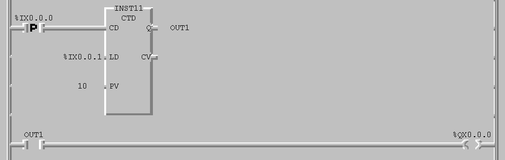
Figure below depicted an example ladder diagram programming use CTD , counter basic instruction


Ladder diagram program above ,maximum value is 1, when input “%Q0.0.0” , then counter will count decremently fro 10 to , so that CV value reach zero or negative value then output counter (OUT1) will on, and output “%Q0.0.0” also on. If input “%I0.0.1” on, the current value (CV) will back to Preset Value (PV) in this chase is 10.

The difference between difference amplifier and instrumentation amplifier

Dear all hands

Some time we need more powerfull amplifier, specially when we deal with transducer that its output is very small such of thermocouple. And the answer Is instrumentation amplifier.
Why difference amplifier did not adequate on such application? The difference amplifer is satisfactory for low impedance source, buts its input impedance is too low for high output impedance sensor. Furthermore , If the input signal very low level and inckude signal noise, the difference amplifier is unable to extract a satisfactory difference signal. The solution is not difference amplifier but instrumentation amplifier.
Instrumentation amplifier has the following characteristic :
a. Instrumentation amplifier has Very high input impedance
b. Large CMMR: CMMR is the ratio of the difference mode gain to the common mode gain. The difference mode gain is the amplification factor for the difference between the input signals, and the common mode gain is the amplification factor for the average of the input signal. For an ideal instrumentation amplifier and difference amplifier , the common mode gain is zero, implying an infinite CMMR. But sure the ideal instrumentation amplifier isnot exist.
c. Instrumentation amplifier has capability to amplify low level signal in noisy environment (due to high CMMR)
d. Instrumentation amplifier has consisten bandwidth over a large range of gain.
Instrumentation amplifier are commercially available as monolithic IC( ex. AD 5234, AD624 or LM 623). In these instrumentation amplifier ICs , a single external resistor is used to set gain.
But theorycally, we can made an instrumentation amplifier using op-amp. There are many instrumentation amplifier circuit design , following figure show an instrumentation amplifier circuit use three op-amp.

Three op-amp Instrumentation amplifier circuit simulation using proteus

Dear all hand

As iam said before that theorically we can build our our instrumentation use op-amp. But its very challenging to simulate our instrumentation amplifer before we make it real. As usual we use proteus isi to build and to simulate our instrumentation amplifer .

Very important for us to use ideal op-amp in build instrumentation amplifier circuit that we want to simulate

What we need is:

  1. 3 ideal op-amp
  2. 6 ideal resistor
  3. 1 Vsine
  4. One potentio

And we arrange components above become three op-amp instrumentation circuit below :


The input and output relationship of the instrumentation amplifier above is :

Applying ohm law to R1 gives :

And we can rearrange equation above become :

And finally we get the output :


In this simulation we take R4= R5 .

To view output and input of this instrumentation amplifier we use oscilloscope (located at left bar of Proteus Isis)

Set V1 (sine ) at 4mV and 10 hz , and run simulate , the simulation result depicted below :


Basic Principle work of transistor current source

Dear all hands

Transistor Current source although often neglected are as important and as useful as voltage source. Transistor current source often provide an excellent way to bias a transistors, an transistor current source are unequaled as “active load” for super gain amplifier stage and as emitter source for differential amplifier.

Integrator, saw tooth generator and ramp generator are need current source. Transistor current source also needed in outside world such of in electrophoresis or electrochemistry.

Basic principle work for current source is the circuit capable to hold current at desired value despite the load is change.

Below is transistor current source circuit with basic principle work :


Basic principle work of transistor current source circuit above is :

  1. Applying VB to the base, with VB > 0,6 v
  2. Ensures that emitter is always conducting :

So

VE =VB-0,6 V

IE = VE/RE = (VB-0,6 v)/RE

But , since IE =IC for very large hfe

IC = (VB-0,6)/RE

From latest expresion, load current in this current source circuit just only depend on RE value, an independent from load value

We can simulate transistor current source circuit above with proteus isis.