Dear all hands
CTD or Counter down
Ladder symbol for CTD :

CD : Down counter pulse input, input trigger for starting counter. When CTD is ON , CTD will count in decrement counting.
LD : Loads preset value,: If LD has value 1 , CV value will be restored as PV value.
PV : Preset Value: is a maximum setting value of the counter. Its range between :-32768 – 32768 , with integer data type.
Q : Down counter output,: counter output that will be executed if the counter reach 0 or negative value..
CV : Current Value, : is the value being displayed when counter incounting condition.
Figure below depicted an example ladder diagram programming use CTD , counter basic instruction
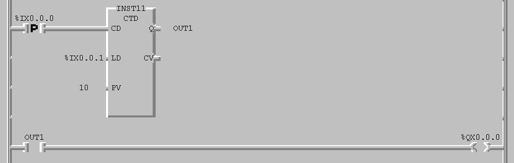
Ladder diagram program above ,maximum value is 1, when input “%Q0.0.0” , then counter will count decremently fro 10 to , so that CV value reach zero or negative value then output counter (OUT1) will on, and output “%Q0.0.0” also on. If input “%I0.0.1” on, the current value (CV) will back to Preset Value (PV) in this chase is 10.
No comments:
Post a Comment